Home » Without Label » Mini Xlr Diagram : Sennheiser Receiver Xlr To Mini Cable Wiring Diagram : A wiring diagram is a streamlined conventional photographic depiction of an electric circuit.
Mini Xlr Diagram : Sennheiser Receiver Xlr To Mini Cable Wiring Diagram : A wiring diagram is a streamlined conventional photographic depiction of an electric circuit.
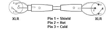
Mini Xlr Diagram : Sennheiser Receiver Xlr To Mini Cable Wiring Diagram : A wiring diagram is a streamlined conventional photographic depiction of an electric circuit.. Xlr 2 (hot) should go to jack tip, xlr 3 (cold) should go to jack ring, xlr 1 (ground) should go to jack sleeve the tn, rn and gn. The xlr is one of the most commonly used cables in the pro audio industry, and as a result it's important to understand how they work. Ford 460 torque mini starter wiring diagram matrix campaign chevy high save diagrams narrate technical imi y block etc the h a m b sbc hobbiesxstyle ko 3277 hitachi get free image about battery ground cable message forum restoration and repair help instructions mustang tech articles cj pony parts third generation f body boards pmgr gary s garagemahal… read more » It reveals the components of the circuit as streamlined shapes, and the power as well as signal links between the devices. Sommer cable neutrik mini xlr 4 pole metal soldering female connector gold plated contact s straight black purchase online.
Check out these specialized audio cables for film production. Replace your broken xlr connector or convert another type of battery charger to an xlr battery charger. Go xlr mini app the go xlr app is required to operate your go xlr mini. K712 and other k701 derivatives like the quincy jones q701. • eq, compress and gate your mic • set up and define mixer controls • change product lighting
PylePro - PMHMS20 - Home and Office - Microphones ... from www.pyleaudio.com Go xlr mini app the go xlr app is required to operate your go xlr mini. Pin 1 = s+b pin 2 = r. • eq, compress and gate your mic • set up and define mixer controls • change product lighting Any interference that penetrates the overall braided screen affects both. 3 5 mm to xlr wiring diagram ref712 jack male stereo 2 x cables are possibly the best choice use as an. Go xlr app key features include: These tiny little solder tabs require care to solder to and see the numbers associated with each pin. Check out these specialized audio cables for film production.
Pin 1 = s+b pin 2 = r connectshield to xlr shell diagram:
K712 and other k701 derivatives like the quincy jones q701. Xlr pin 2 to 1/4 plug tip. These tiny little solder tabs require care to solder to and see the numbers associated with each pin. Mx 3 pin 4 pin & 5 pin mini xlr type connector is a type of connector used for many professional audio applications. This can be done by either soldering the shield and negative wires of the xlr to the sleeve of the plug. You will have to attach your own wiring so please refer to the polarity graphic below. Diy audio electronics from zynsonix com balanced xlr to rca cable in wiring diagram how to wire an xlr two rca connectors 3 pin mini xlr wiring diagram solutions lovely xlr wiring diagram male pin 4. Mx 3 pin 4 pin 5 pin mini xlr type connector is a type of connector used for many professional audio applications. North america amphenol audio representative office 44724 morley drive clinton township, mi, usa 48036 p +1 800 394 7732 or +1 586 913 8650 When it comes to studio wiring you can save a lot of money by doing it yourself, and being able to fix an xlr in the field is a great skill to have. Pin 1 = s+b pin 2 = r connectshield to xlr shell diagram: The xlr is one of the most commonly used cables in the pro audio industry, and as a result it's important to understand how they work. Pin 2 on the xlr is 'hot' and carries the positive going signal, whilst pin 3 is 'cold' and provides the return.
K712 and other k701 derivatives like the quincy jones q701. Amphenol 1/4″ trs, 3.5mm trs, neutrik 4 pin xlr, 4.4mm trrrs (pentacon), or 2.5mm trrs. Sennheiser receiver xlr to mini cable wiring diagram the absolute correct, proper wiring for a transmitter mini plug fed from a. It would be extremely dangerous. 3 5 mm to xlr wiring diagram ref712 jack male stereo 2 x cables are possibly the best choice use as an.
Wiring Color Diagram On A Usb Microphone | USB Wiring Diagram from usbwiringdiagram.com Xlr pinout (balanced) a balanced system is used in pro audio systems (xlr wiring diagram shown below), with an overall screen covering a twisted pair. You'll also discover each xlr pin's polarity. 3 pin xlr wiring standard. Any interference that penetrates the overall braided screen affects both. Some manufacturers, especially in vintage equipment, do not follow this standard and instead reverse the polarity of pin 2 and 3. Amphenol 1/4″ trs, 3.5mm trs, neutrik 4 pin xlr, 4.4mm trrrs (pentacon), or 2.5mm trrs. Mx 3 pin 4 pin & 5 pin mini xlr type connector is a type of connector used for many professional audio applications. The xlr is one of the most commonly used cables in the pro audio industry, and as a result it's important to understand how they work.
Xlr pinout (balanced) a balanced system is used in pro audio systems (xlr wiring diagram shown below), with an overall screen covering a twisted pair.
Microphone madness dual xlr female to 1 8 3 5mm mm dxlrf 35sm. A wiring diagram is a streamlined conventional photographic depiction of an electric circuit. (the rear view is the end you solder from) here are the connections on each pin: Since each driver only needs a signal and ground, and each mini xlr has four pins, the pins are shorted so that the signal uses pins 1 and 4 and the ground uses 2 and 3, as seen in the below diagram. I modified a cl rx(trs) to balanced xlr cable so i could use it with my personally i prefer feeding the wireless from the mixout ta3 which is at. Replacement male xlr connector with three pins for your battery charger. In addition, it may be helpful to label the wires prior to disassembly. This wiring configuration gives you a balanced mono audio cable. Xlr to 1/4 mono plug. Xlr pin 1 to 1/4 plug sleeve. Bridging 1&4 for signal, 2&3 for ground) 2. Available in lengths up to 15ft. Welcome connection diagram about this document this quick start guide will help you set up, connect and begin operating your go xlr mini.
• eq, compress and gate your mic • set up and define mixer controls • change product lighting Microphone madness dual xlr female to 1 8 3 5mm mm dxlrf 35sm. 3 pin xlr wiring standard. Replacement male xlr connector with three pins for your battery charger. Bridging 1&4 for signal, 2&3 for ground) 2.
Microphone Characteristics from www.esr.co.uk This can be done by either soldering the shield and negative wires of the xlr to the sleeve of the plug. Collection of xlr to mono jack wiring diagram. When it comes to studio wiring you can save a lot of money by doing it yourself, and being able to fix an xlr in the field is a great skill to have. Welcome connection diagram about this document this quick start guide will help you set up, connect and begin operating your go xlr mini. Check out these specialized audio cables for film production. 5 pin & 3 pin xlr wiring pinout information. Xlr to 1/4 mono plug. 3 pin xlr connectors are standard amongst line level and mic level audio applications.
This can be done by either soldering the shield and negative wires of the xlr to the sleeve of the plug.
I modified a cl rx(trs) to balanced xlr cable so i could use it with my personally i prefer feeding the wireless from the mixout ta3 which is at. Ref712 3 5 mm jack male stereo 2 x xlr. Mx 3 pin 4 pin & 5 pin mini xlr type connector is a type of connector used for many professional audio applications. Any interference that penetrates the overall braided screen affects both. The above diagram shows you the pin numbering for both male and female xlr connectors, from the front and the rear view. Xlr to 14 trs connector wired for balanced mono the usual way to connect a 3 pin xlr to a 14 trs aka stereo jack plug is to use the following pin allocation. Xlr pin 2 to 1/4 plug tip. K712 and other k701 derivatives like the quincy jones q701. 3 pin xlr connectors are standard amongst line level and mic level audio applications. 3 pin xlr wiring standard. Pin 1 = s 10k pin 2 to w 1uf pin 2 to w connectshield to xlr shell diagram: These tiny little solder tabs require care to solder to and see the numbers associated with each pin. Amphenol 1/4″ trs, 3.5mm trs, neutrik 4 pin xlr, 4.4mm trrrs (pentacon), or 2.5mm trrs.